- Published on
Orbitron: Reinventing the (spherical) wheels and its control algorithm
- Authors
- Name
- Tyler Kim
- @tylertaewook


Being a heavy Sci-fi fan myself, I always wondered: how would those spherical wheels from Tron and I-Robot work in real life? And this simple thought began the 6-month journey of Project Orbitron.
Now, this project consisted of two major goals upon start:
- Building a vehicle with spherical wheels that implement a 4 wheel independent steering/driving (4WIS/D) system using Arduino
- Developing an intuitive control algorithm for 4WIS/D vehicle in Mathematica
This article will showcase my vehicle prototype Orbitron along with a short story behind the building scene. Then, I'll introduce you to the highlight: a clever algorithm I built to control Orbitron seamlessly.
You can also check out this maker portfolio video I made for my college application or checkout the github repo containing the full code.
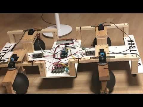
Orbitron
As I mentioned above, ORBITRON is a vehicle with spherical wheels, hence the name 'ORB'itron. Unfortunately, I was a bit under-qualified to suspend wheels in mid-air with electromagnets, as many sci-fi movies suggested. Instead, I implemented a 4 Wheel Independent Steering/Driving (4WIS/D) system: a steering system for a four-wheeled vehicle that allows for separate speed and direction controls for each wheel.

Structure
Wheels
After an initial sketch of the wheel's frame, I modeled the same design in Fusion 360. I designed the frame to house two separate motors, each controlling speed and direction, to steer and drive the wheels independently from others.

I used a 60mm EVA-foam ball as wheels since they were light yet sturdy enough to support the vehicle. The HS-785HB servo with a built-in gearbox on the top controls the wheel’s direction by turning the motor's entire rectangular structure. The 170-RPM Econ Gear Motor directly connected to sphere's shaft takes care of driving the wheel and controlling the speed.

Body
Designing the body was relatively simple, as it was simply a rectangular board supporting the wheel frames.

I built the body out of MDF board at first, but it proved to be too heavy. So I changed into Foamex board supported by PVC pipes which was much lighter and stronger.

To continue working on this project during summer vacation when I flied back to Korea, I carefully designed the board to be foldable to make overseas shipping easier. This way, I just had to detach the wheel frames, fold the board up, and cover with bubble wraps when shipping.
Electronics
Arduino
I won't go into too much detail in the wirings here. Shortly put, the Arduino Mega is connected to XBee shield for wireless communication, two Motor Drivers for controlling the driving motors, and four servo motors for steering each wheel.

Controls
While building, I developed a simple C# WinForms application to ensure each component was functioning properly. This app would send alphabet signals through XBee wireless module, and Orbitron would perform pre-set movements such as rotating all servos 180 degrees when received 'r' character.

Algorithm
The real beauty of this project was the algorithm development. The following writings will summarize my paper: "Intuitive Control Algorithm Development of 4WIS/4WID Using a SpaceMouse"
4WIS/D system of the Orbitron enables more versatile motion for vehicles that needs to navigate in tight spaces but controlling two parameters, direction and speed, for each wheel results in eight parameters in need of simultaneous control.
So our goal was simple: to develop an algorithm that achieves an Intuitive control that abstracts away the complexity, allowing for a full realization of the vehicle's capabilities.
Algorithm Setup
We chose 3Dconnexion's SpaceMouse (SpaceNavigator) as a controller as it was designed for intuitive navigation on 3D space in CAD.
Connecting the SpaceMouse with Mathematica gave us six numbers ranging from -1 to +1 based on the mouse's position, which became the raw input data for our algorithm.

The algorithm’s main job is to translate these six variables from the SpaceMouse to eight variables, each of which represents either angle or speed of a wheel. The algorithm is responsible for calculating variable transformations and records the sets of timestamped variables in a CSV file. We then use a serial regulator, a C# application I've developed, to deliver the set of variables at a proper time without overfeeding data to the prototype.

When Mathematica Notebook is executed, the interface on the right is continuously updated based on the user’s input. All the arrows shown in this interface are color-coded differently to distinguish each other more effortlessly. Four labels are shown next to each wheel to display updated angle and speed values.
Green Concentric Circles: each represent the radius of curvature of each wheel and the center of the vehicle. This can be applied to vehicles with any number of wheels, but just with more curvature circles.
Blue Arrow: motion of the vehicle's center
Gray Arrow: acts as base for red/pink arrows; always fixed along the vehicle body's angle
Pink Arrow: tangent line of the green circle; angle between the gray arrow and pink arrow is used to determine each wheel's angle
Red Arrow: actual trajectory of the vehicle; As user controls the mouse, arrows' length will always represent the relative velocity of each wheel.
Implementing Different Steering Modes

While the conventional steering system only involves Ackerman Steering, 4WIS/4WID can have three different steering modes: AFRS, Crab Steering, and Spinning. Our algorithm supports all three steering modes and allows us to simultaneously control all four wheels without any danger of movement conflicts. We do so by computing both the wheel’s direction and speed based on the wheel’s angular velocity during a turn. This prevents any conflicts between the signals that can result in a vehicle slipping.
Crab Steering
Crab steering is a special type of active four-wheel steering that operates by steering all wheels in the same direction and at the same angle.

The algorithm uses the Crab steering mode whenever the user slides the SpaceMouse on the plane. In this specific example, when the mouse is facing upper right corner, all four wheels are angled in the direction the mouse is pointing at. All four wheels have the same speed which is computed as the tangential velocity of a circle with a very large radius.
Active Front and Rear Steering
AFRS mechanism involves front and rear wheels turning independently for smaller turning radius and better cornering stability. In this steering mode, rear wheels change the way a vehicle turns based on driving parameters. Each wheel’s velocity is computed as the tangential velocity of a circle.

The twisting motion of the SpaceMouse is responsible for changing the radius of the vehicle’s curvature. The core of the algorithm is that it considers every motion as a circular motion and computes each wheel’s velocity and angle tangent to that circle. The radius of curvature (𝒓) is calculated by the equation shown above, and the angle value (θ) is controlled with the twisting motion of the mouse.
When the mouse is twisted clockwise, θ is increased, resulting in a larger curvature radius. When the mouse is twisted counterclockwise, θ is decreased, resulting in a smaller curvature radius. Negative θ will make the circle move in the other side of the vehicle.
This principle also applies to straight motion in scenarios such as Crab Steering mode. Continuously twisting the mouse counterclockwise will make θ very small, leading the turning radius to be almost infinite. At this point, the vehicle’s motion will be considered to be a straight motion.

In these examples, straight motion and curving motion are accomplished simultaneously. When twisting and shifting the mouse occurs at the same time, the vehicle can perform more complicated motion, such as moving forward with a gradually decreasing turning radius.
Spinning
Also known as the Zero Turn mode, Spinning is the motion of a vehicle rotating with zero radius. It is easily accomplished by turning all wheels perpendicular to the center diagonal line and turning the wheels in the same direction.

When one of the two buttons on the side of the SpaceMouse is pressed, the vehicle rotates in the respective direction. As shown in the screenshots above, the vehicle turns in a clockwise direction when the right button is pressed, and the vehicle rotates in a counterclockwise direction when left button is pressed.
Conclusion
In six months, I built a prototype vehicle and experimentally confirmed that our algorithm successfully processes the driver’s intention conveyed by a SpaceMouse and cooperatively controls all four wheels so that they don’t conflict with each other to accomplish the intended motion.
I have worked on several for-fun projects in Arduino before, but Project Orbitron was by far the largest and most complex one I have ever done. Building the prototype alone took the entire summer vacation and over $1,000 in the budget. I spent another three months developing the algorithm while teaching myself Mathematica and constantly tweaking Orbitron's settings.
Upon finishing the project, I participated in a local science fair and presented my work to the Kent Guild, an academic society at my school.
Project Orbitron has become the core experience/project of my journey and ended up being the main topic for my college essay. The prototype is currently displayed on the first floor of Kent School's Pre-Engineering Center, and my algorithm is going through a patent process in Korea. (Application Number: KR 10-2019-0087022)